

Pressures inside the Extruder
The pressures inside the extruder reflect the flow that occurs in the extruder. Figure 1.8 shows the flow in a cross section of the screw channel in the metering section of the extruder. At the top of the channel there is a drag flow toward the pushing flight flank and the pressure increases from P4 at the trailing flight flank to P1 at the pushing flight flank. At the pushing flight flank, material will move toward the root of the screw by pressure flow. As a result, pressure P1 will be greater than pressure P2 at the bottom left of the screw channel. At the lower portion of the screw channel material will move to the trailing flank of the flight by pressure flow because pressure P2 is greater than pressure P3. There is pressure flow along the trailing flank of the flight because pressure P3 is greater than pressure P4.
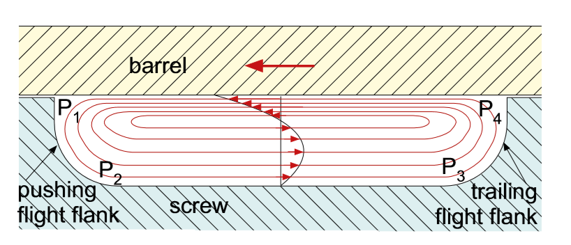
Figure 1 :Cross channel flow in single-screw extruder
The highest pressure in the channel is pressure P1 and the lowest pressure is pressure P4. This is the pressure drop across the flight. This pressure drop ΔPx =(P1−P4) can be expressed as follows for a Newtonian fluid:
In this expression μ is the melt viscosity, vb is the barrel velocity, Wx is the width of the channel, f is the flight helix angle, and H is the depth of the channel. This pressure drop ΔPx depends on the viscosity, screw geometry, and screw speed. When the screw geometry and screw speed are known, the viscosity can be determined from the pressure drop ΔPx. When pressure is measured in this part of the extruder, the pressure will have a saw tooth pattern as shown in Figure 2.
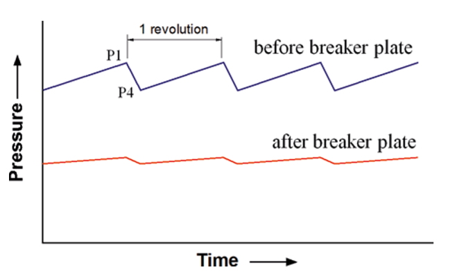
Figure 2: Pressure versus time in the metering section
The time between peaks equals the time for one screw revolution for a single flight screw. This means that the screw speed can be determined from the pressure trend. For a double-flighted screw there will be two pressure peaks for each revolution of the screw.
The pressure pattern in the melting zone of the extruder will be different because the screw channel is not only filled with molten polymer but also un melted polymer. In a single-screw extruder the melting usually occurs by contiguous solids melting or CSM. In contiguous solids melting the solid particles are compressed together in a solid bed, see Figure 3. The solid bed forms a helical solid ribbon that wraps around the screw. As melting progresses the size of the solid bed reduces while, at the same time, the size of the melt pool increases. There is a thin melt film between the solid bed and the barrel. Most melting takes place at the interface between the solid bed and the melt film.
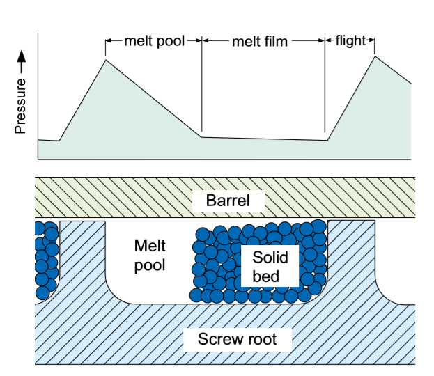
Figure 3 :Contiguous solids melting and pressures
If pressures are measured in the melting zone, the pattern will be different from that of the melt conveying zone. The pressure gradient in the melt film will be different from the pressure gradient in the melt pool as shown in Figure 3 Therefore, when pressure is measured midway along the barrel, the pressure pattern reflects the location of the solid bed, the melt pool, and the flight. By locating several pressure transducers along the length of the barrel, the progress of melting along the length of the extruder can be analyzed.
Ref: Troubleshooting the Extrusion Process(Noriega / Rauwendaal)


